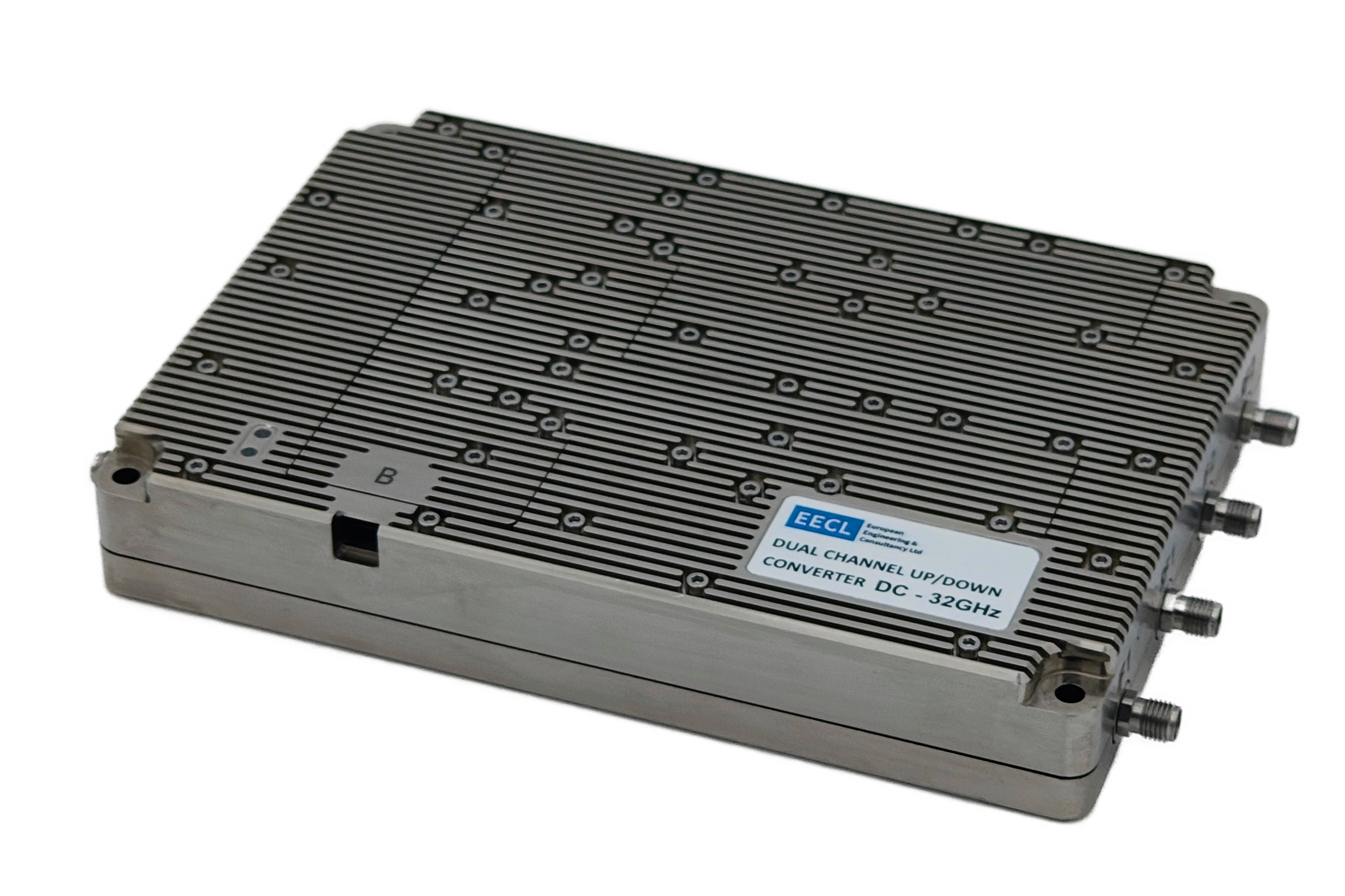
EECL’s Dual-Channel DC-32GHz Frequency Converter is a highly-integrated and highly-configurable solution for frequency conversion up to Ka-Band.
Featuring a ultra-low phase noise tunable LO, gain control, and integrated image and LO rejection filters, the device offers a one-module solution for a wide-range of use cases.
The module can be integrated into our rack mounted switch matrix if required.
A simplified (equivalent) system block diagram of the converter is shown below. The two branches are identical and are fed by a single LO. This ensures we get correlated gain and phase. Each arm has a switched filter bank to remove unwanted sidebands and LO leakage. There is gain on the RF path for output and input (reversible) but only gain on the IF path for output. This is because the intended use of the converter is to come from known stronger lab equipment and therefore IF input gain is not required.
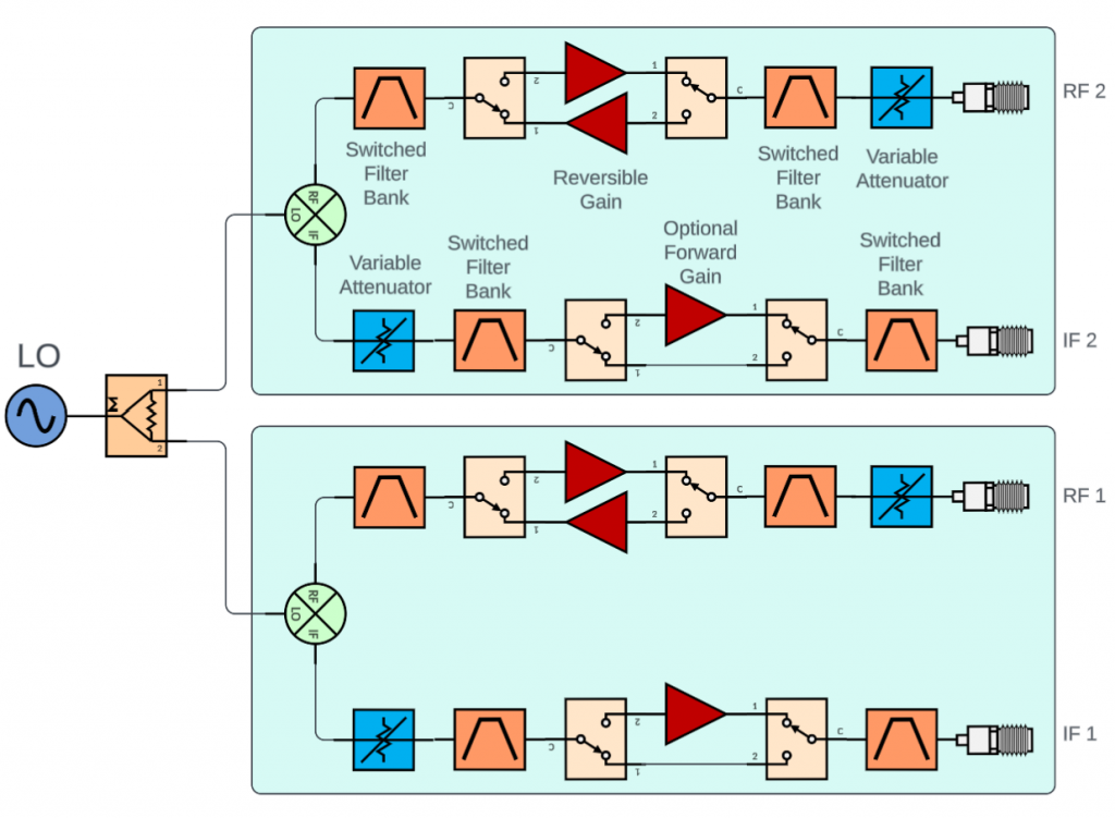
The attenuators provide up to 60dB of attenuation range. At minimum settings the overall conversion gain is around 5dB positive depending on the particular band being operated. The RF ports are capable of around +3 dBm output power.
The RF port has a 0, 16, 32 or 48dB selectable attenuator and it is capable of handling high input powers up to 26dBm whilst maintaining linearity.
For up convert the IF port the input power should be set between -30dBm and 0dBm for maximum SNR on the RF port.
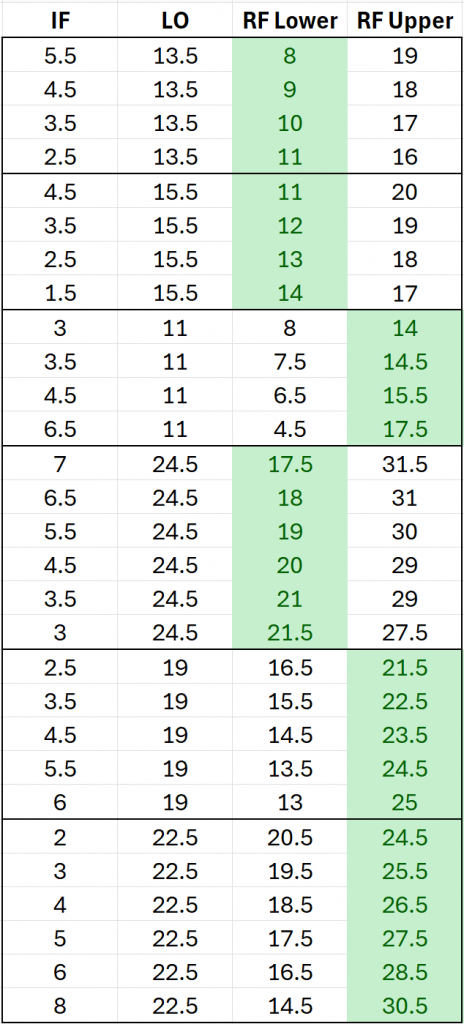
The Local Oscillator (LO) is highly versatile, supporting a range from 8 GHz to 32 GHz with a 1 MHz step resolution. The system supports both up-conversion and down-conversion across the following frequency ranges:
While the system supports any mathematical combination of these frequencies, we recommend using the configurations provided in the table below to ensure optimal performance and maximum spur/image suppression.
Note: The table below highlights several optimized configurations, but it is not an exhaustive list. The system supports a virtually infinite number of frequency combinations. For unique frequency plans, we can also customize the image rejection filters upon request to ensure peak performance.
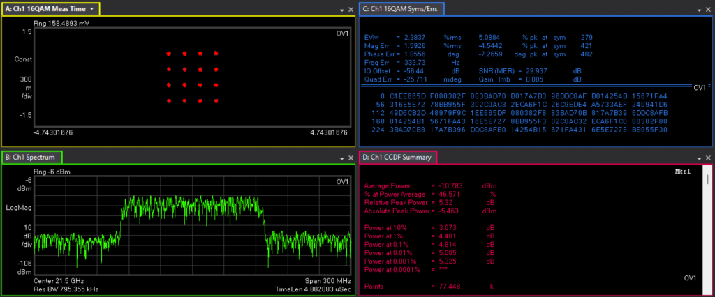
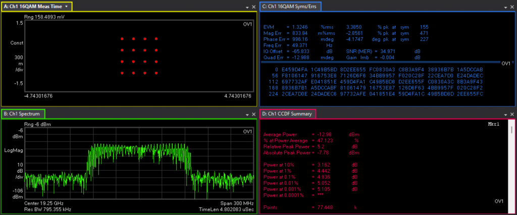
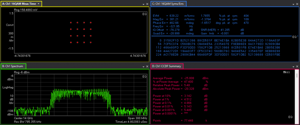
The following plots show a modulated signal of 125MHz bandwidth being upconverted. The EVM is measured and it can be seen that the total distortion of the chain is extremely pure.
It can be seen that the converter can convert a signal at 14GHz, 19GHz, 12.5GHz and 30GHz with EVM of 41.2dB, 35dB, 30dB and 31dB respectively.
The following plots show the upconverted and down converted conversion gain and flatness.
The following plots show the spectral purity for various up and down conversions.
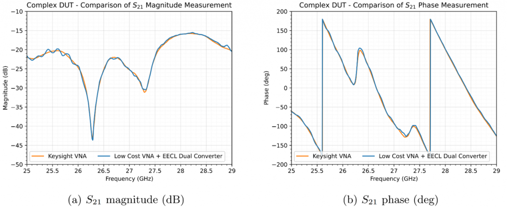
The converter can be used as a VNA frequency extender (for S21 measurements) in applications such as antenna anechoic chamber measurements.
This allows an extremely low-cost measurement system to be used with practically identical measurement quality. The plot below shows our Dual Converter with a Low-Cost Low-Frequency VNA, compared to a High-Cost Keysight VNA. For more information on this VNA frequency extension technique, please consult EECL Application Note AN2501, available below:
EECL provides a wide suite of available software control options, including both graphical user interfaces (GUIs) and scripting libraries. Options include, but are not limited to:

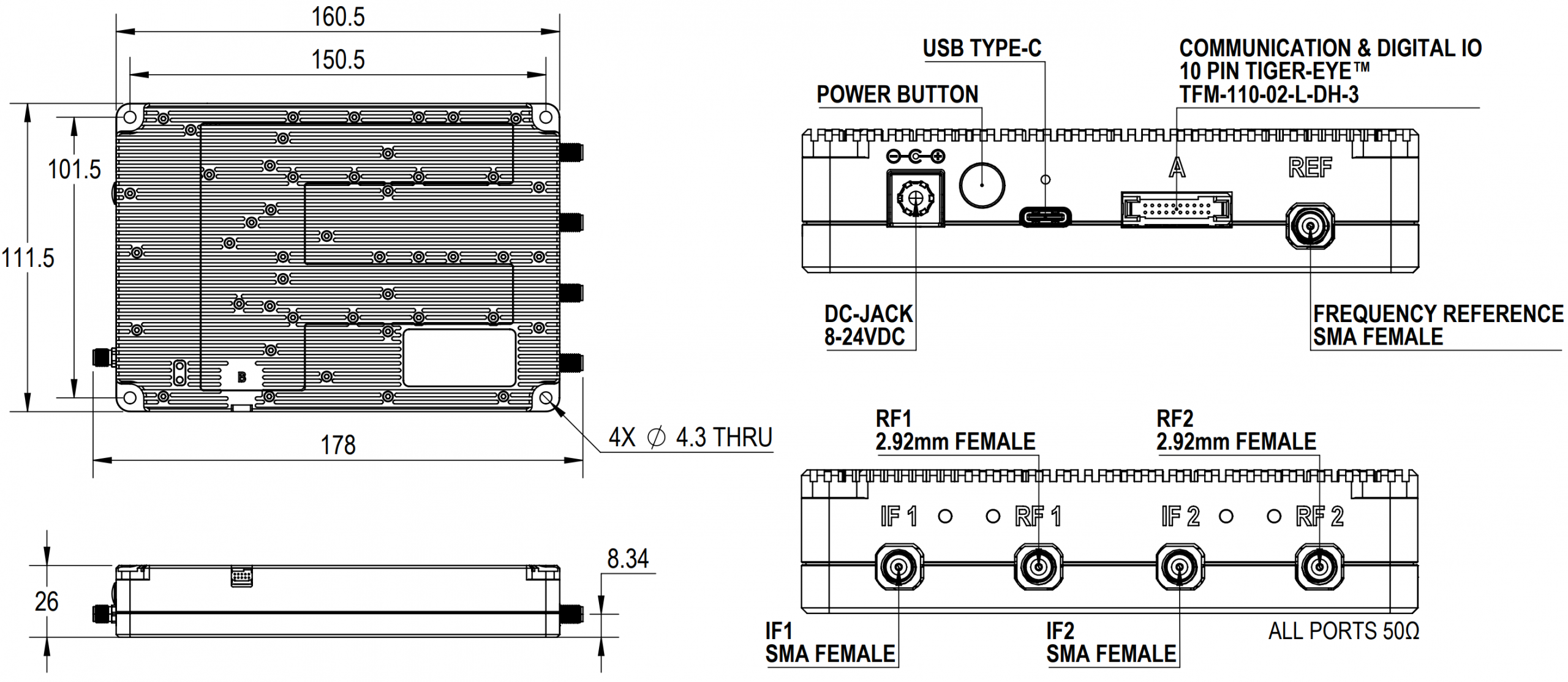
Unit dimensions are as shown below: